Analysis of a Remote Control
A couple of days ago I found some old remote controls around the house and decided it was time to take out my old RTL-SDR and put it to good use. In this article I will describe step-by-step my experience with studying, reversing and understanding these devices.
In particular the analysis will comprehend:
- Analysis of the board
- Analysis of the behavior
- Analysis of the signal
This will allow to have a complete overview of the remotes.
 |
|---|
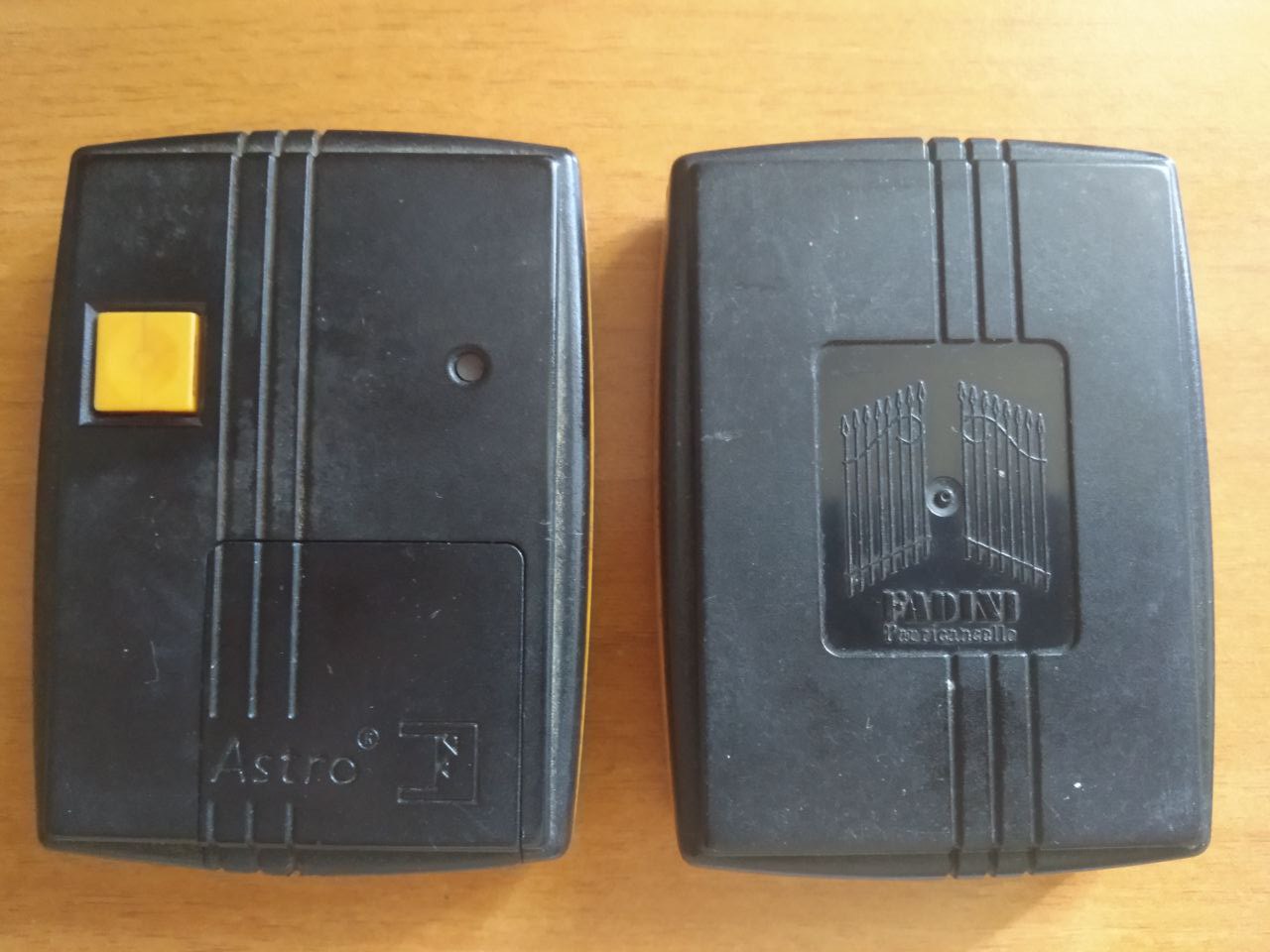
| Remote to analyze |
Board analysis
The first thing I did was to operate the remote: of course whenever the yellow button was pressed, the led on its side would light up signaling that everything was working fine. The device could use different communication methods, but since there is no visible IR LED, it is possible to assume that the device works via radio signals.
The very next step was to open up the remote and visually inspect the board.
Inside the plastic casing I found this simple PCB.
 |
|---|
| PCB board |
At first glance it’s possible to notice that there’s an antenna, a crystal oscillator, a trimmer an integrated circuit and of course led, button and battery. As expected, there’s everything needed for a radio transmitter to work.
 |
|---|
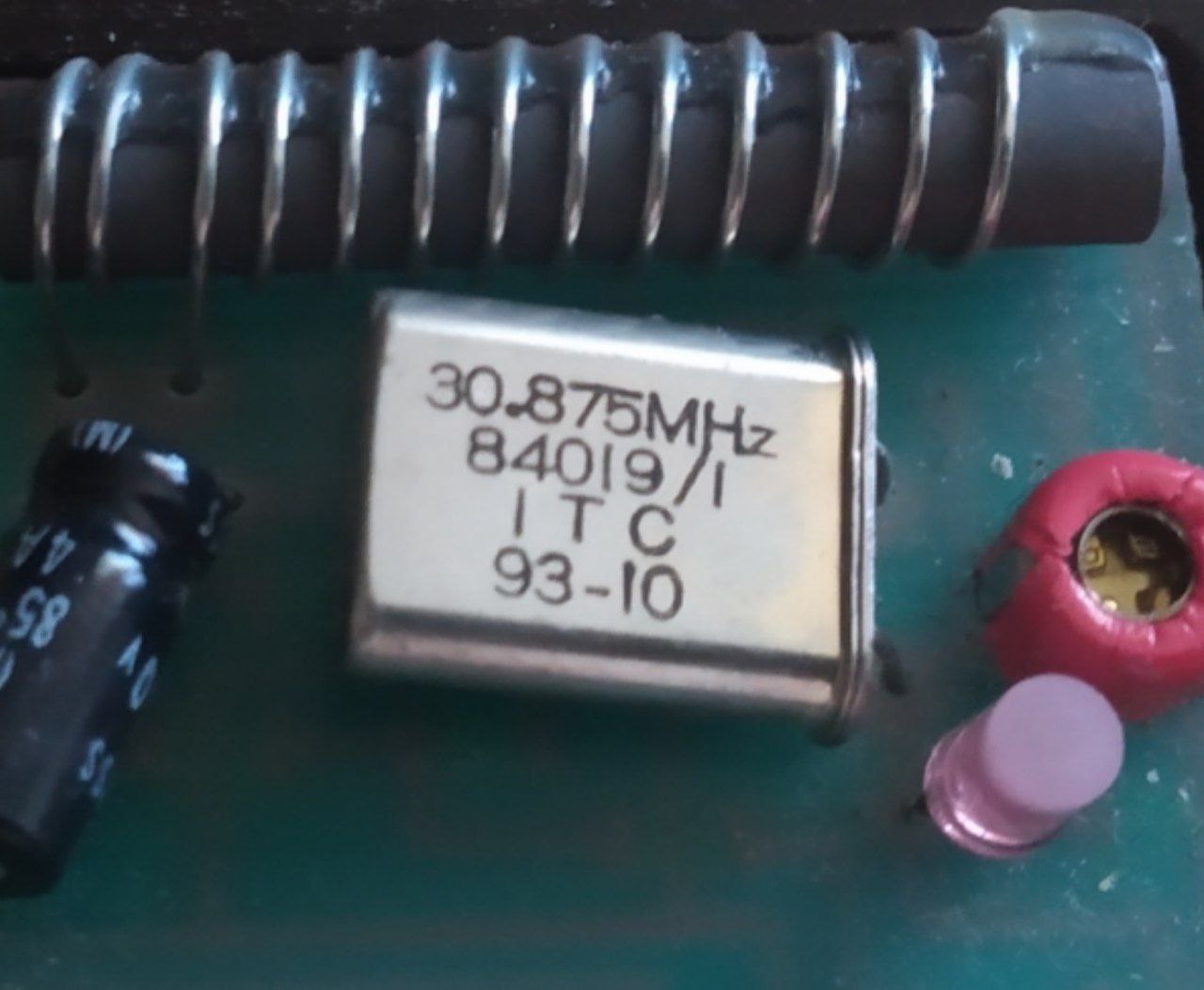
| 30.875MHz oscillator |
Looking at the components further it’s possible to gather insights about how the device works. In particular the oscillator gives away that the device probably operates at 30.875MHz - this isn’t what I was expecting.
In my country, Short Range Devices should work in the ranges:
- 27,5000 – 28,0000 MHz
- 29,7000 – 30,0050 MHz
Or, for general purpose applications they can work in the ranges:
- 433,000 – 435,0000 MHz (devices without a specific use)
- 862,0000 – 876,0000 MHz (devices without a specific use, wireless audio, alarm systems, social alarms, radio microphones, and RFID devices)
Radio transmitters are not forced to adopt the crystal oscillator frequency as working frequency, in fact it’s not uncommon that they use a multiple of such frequency instead. Said that, at this point it’s only a guess, but even if it’s not in the expected ranges, it’s possible that the working frequency of the remote would be around 30.875MHz.
 |
|---|
| 10-position DIP switch |
We can also see that there’s a 10-position DIP switch.
The first pin (1) of the DIP switch has written “ON” on top of it, meaning that the switch closes the circuit when the lever is in the “high” position. This component suggests us that the remote sends at least 10 bits of data. I say at least, because it’s possible that the device sends preamble/ending bits and/or checksum or parity bits.
Also, given the position of the switches, it’s possible to assume that the code sent by the remote would either be 0001000110 or 1110111001.
 |
|---|
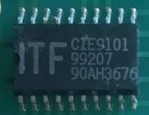
| ITF CIE9101 Integrated Circuit |
On the back of the PCB there’s the ITF CIE9101 integrated circuit. Sadly I wasn’t able to find any datasheets or information about this component (hit me up if you know something about it!).
Inspecting the PCB it’s possible to see that this device is connected to the DIP switch, to the oscillator and to the antenna. We can make an educated guess and say that this IC is probably responsible for the radio transmission (in future it would be worth reverse engineering this IC to better understand how this device work).
Behavior analysis
To validate the hypothesis of the device being a radio transmitter, it’s fundamental to try to intercept and visualize the communication.
The goal now is to find the transmitted signal. There is a limited set of possible frequency ranges, but it’s not always easy to blindly spot the signal you’re looking for, especially in areas in which similar devices are widely employed (think of remote car keys, AC remotes, radio weather stations and so on).
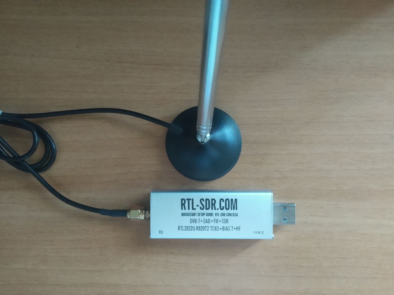
To figure out the frequency and to work with the raw radio signal I used a Silver dongle RTL-SDR and gqrx.
 |
|---|
| RTL-SDR and Antenna |
Once gqrx was open, it was necessary to spot the correct frequency. Since there is a 30.875MHz crystal oscillator in the remote, that was the first frequency I checked. And luckily the signal was right there. Well, for this remote in particular it was at 30.889MHz, but at least we got the working frequency.
NOTE: I could work with 3 of these remotes, and each one was using a slightly different frequency, that’s why it was possible to find the signal at 30.889MHz and not exactly at 30.875MHz. This can depend on a number of factors and it’s completely normal.
 |
|---|
| Signal interception |
Now it’s time to analyze the signal.
Signal analysis
What I did at this point was to record the signal in gqrx to analyze it. Opening the signal in audacity shows the recorded waveform.
 |
|---|
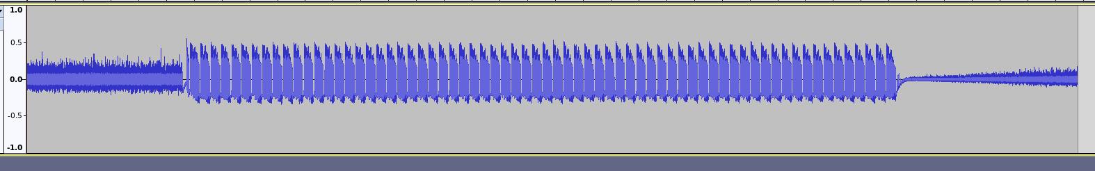
| Signal waveform |
We can see noise at the beginning and at the end of the recording, while the center part represent the communication.
It’s possible to notice immediately that there are numerous spikes, this is due to the fact that I kept the button pressed for a few seconds while recording. Visually it’s possible to say that the spikes are identical, so our scope is limited to understanding what one of these spikes represent.
Now we need to zoom in on one spike to try and decode the actual digital data.
 |
|---|
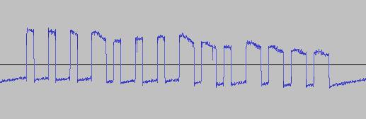
| Zoomed waveform |
Of course it’s a digital communication and It’s now clear that we are dealing with Pulse Width Modulation (PWM). If we look closely at the signal, we can see that there are “short” and “long” pulses. Those represent either 1s or 0s depending on the protocol shared by the remote and the receiver.
Counting the bits reveals that that’s more than a simple 10 bit communication. In fact, we are dealing with 14 bits. If we compare the signal to the position of the switches in the remote, we see that the pattern matches, with the exception of the last 4 bits. These bits (either 0000 or 1111) are trailing bits, needed to signal the end of the communication.
To prove that the signal actually corresponds to the one encoded by the switch + 4 trailing bits, I’m using rtl_433 to read and decode the signal.
So we run rtl_433 -f 30888000 -A and we get this output:
Attempting demodulation... short_width: 748, long_width: 1516, reset_limit: 5420, sync_width: 0
Use a flex decoder with -X 'n=name,m=OOK_PWM,s=748,l=1516,r=5420,g=1556,t=307,y=0'
pulse_demod_pwm(): Analyzer Device
bitbuffer:: Number of rows: 6
[00] {14} ee 40     : 11101110 010000
[01] {14} ee 40     : 11101110 010000
[02] {14} ee 40     : 11101110 010000
[03] {14} ee 40     : 11101110 010000
[04] {14} ee 40     : 11101110 010000
And we confirm that the signal uses a PWM modulation and is in fact 1110111001 followed by 0000.
To exclude the possibility that the last 4 bits are parity bits, we need to try other configurations in the remote and analyze the signal. I proceeded to do so and one-by-one I lifted the switches corresponding to the 0s in the signal to see what would change in the transmitted bits.
Changing bit 9 from 0 to 1 produced the following signal:
[00] {14} ee c0     : 11101110 110000
[01] {14} ee c0     : 11101110 110000
[02] {14} ee c0     : 11101110 110000
[03] {14} ee c0     : 11101110 110000
[04] {14} ee c0     : 11101110 110000
[05] {14} ee c0     : 11101110 110000
Similarly, changing bit 8, produced this signal:
[00] {14} ef c0     : 11101111 110000
[01] {14} ef c0     : 11101111 110000
[02] {14} ef c0     : 11101111 110000
[03] {14} ef c0     : 11101111 110000
[04] {14} ef c0     : 11101111 110000
[05] {14} ef c0     : 11101111 110000
Finally I changed bit 4 and I decoded signal was:
[00] {14} ff c0     : 11111111 110000
[01] {14} ff c0     : 11111111 110000
[02] {14} ff c0     : 11111111 110000
[03] {14} ff c0     : 11111111 110000
[04] {14} ff c0     : 11111111 110000
[05] {14} ff c0     : 11111111 110000
As I suspected the last 4 bits don’t change even if the signal changes. This means that they are simple trailing bits and not parity bits or a form of checksum.
Conclusions
After the analysis, everything about how this board operates is known. Since this device was pretty old I wasn’t expecting behaviors any more complex that the ones we observed.
I was left with a deeper understanding on radio communications, in particular of the concept of modulations. This was in fact the first time I was confronted with the PWM modulation in a real life scenario. Decoding these signals both visually and using specialized software allowed me to learn new tools I’ll be using for future experiments.